Monday
Oct182010
On Hold for School:(
 Roeurn Tourn
 I couldn't finish before classes start, I'll try to work on it again during the Christmas Break.
Roeurn Tourn I couldn't finish before classes start, I'll try to work on it again during the Christmas Break.
Roeurn Tourn Main schematic and PCB layout has been accomplished. And the BOM (Bill of Materials) was built. Of course once ICs are selected, the support electronics have to be identified on the BOM as well. Everything took longer than I expected, but I’m done. Parts selection, schematic outline, and pattern design took 80% of my time. The actual layout was short in comparison. 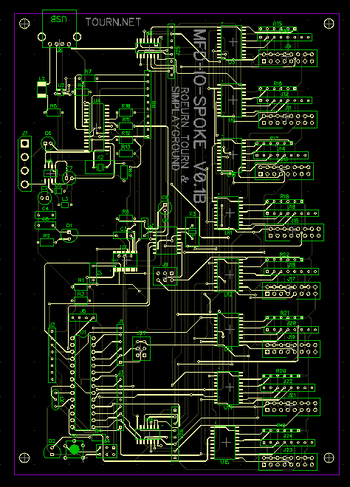
I’ve built the NC Drill and Gerber files and uploaded them to Sunstone last night. The board and component cost were high. Two boards were ordered, with the required parts plus a 10%-30% overage totaled $571. Woo. This is of course version 0.1B. By making this board into an Arduino shield, with a PS/2 output, we can reduce cost by 60% or more.
In the mean time waiting for the boards to arrive, I’m going to tapping into the MFD ribbon cables with my logic analyzer.
Please note that all work on this site is licensed Creative Commons Attribution-ShareAlike 3.0.

MFD-IO-SPOKE by Roeurn Tourn is licensed under a Creative Commons Attribution-ShareAlike 3.0 Unported License.
Based on a work at www.ladyada.net.
Roeurn Tourn ;) The main task is to enable the button control on the MFD and joystick to produce a re-programable keystroke event. Virtually any game sold can respond to a keyboard, thus making this system emulate a keyboard allows the system to have instantaneous compatibility with many game systems. The re-programability is handy to quickly convert from one game to another. Making the system open source allows customizability, and open to organic community generated solutions.
The main task is to enable the button control on the MFD and joystick to produce a re-programable keystroke event. Virtually any game sold can respond to a keyboard, thus making this system emulate a keyboard allows the system to have instantaneous compatibility with many game systems. The re-programability is handy to quickly convert from one game to another. Making the system open source allows customizability, and open to organic community generated solutions.
I chosen to use an Arduino core as an open source hardware heart of this project. I couldn’t find a Arduino USB keyboard emulator library, but there are open source libraries for a PS/2 keyboard emulator. I chosen to use this library, and convert the PS/2 signal to USB via a dedicated IC.
In creating the Arduino Core, I borrowed heavily from Lady Ada’s work on the USB Boarduino. We will maintain a serial connection (at least after boot-up) to the Arduino with the same serial over USB connection that used in the Duemilanove board. I say “at least after boot-up”, because I will use all the outputs, including the RX, and TX lines for the IO bus.
In my continuity testing, I’ve noticed that the LED output enable pins are tied to one pin on the ribbon cable. This must be accessed individually, so they go through a shift register.
Roeurn Tourn This portion took a number of days and in some ways is ongoing. The MFDs are separated into two sub-systems: CRT display, and button & LED IO. Each system is logically separated and do not interact between each other. I’m only concerned with the Button IO.
The button IO subsystem contains a board called a Button Board, with 8 connectors for the LED buttons on top, and a DB-16 connector on the bottom. A jumper on left is used to distinguish between different button boards on the same ribbon cable. There are 7 solid state logic ICs on the board. They are listed below in order of logical significance. ;)
U1: 74HCT164 8 bit serial-in parallel out shift register
U2: GD54HC00 quad 2 input NAND gate
(used with the jumpers as part of board selection process)
U3: 5821 8 bit serial in Latched Drivers
U5: 5821 8 bit serial in Latched Drivers
(used to output to the LEDs)
U6: CD74HC165 8 bit parallel-in Serial out Shift register.
U7: CD74HC165 8 bit parallel-in Serial out Shift register.
U4: HD7405P HEX inverter
(used as part of the button input, and outputting circuit to the RIO board)
The intermediate goal is to draw a schematic of the button board. Simply looking at the traces is hampered by the plastic bits of the sockets and headers. I would like to x-ray of the board and redraw the schematic from the traces. (To overcome this problem in the future I think I want to build an x-ray machine at some point. )Having a schematic would allow me to figure out the cable used to communicate over the cable.
For now I only need to know what pins are the input pins and what pins are output pins so I could begin drafting the circuit board to control this device. Because the system uses solid state logic it is possible to determine uses and protocols by the arrangement and presence of the ICs on the board. Each chip has an designated input pin and an output pin.
 To find these pins, I took the board, my multimeter and went to Starbucks. A vanilla mocha and some time doing continuity testing, allowed me to determine that most of the lines on the db-16 line were power and ground, one line was attached to all the CLK inputs on all the ICs, and input 3 data lines, with 1 data output line .
Knowing witch is input and output is all I need to begin building a replacement board to interface the MFDs. More on that in the next post. And yes, they did misspell my name:)
Roeurn Tourn The pods themselves are made from plywood. The hinges, the rollers, are all standard stuff that you can get from any hardware store. The wood is painted black. The outer casing of each pod, is made from a thick gray plastic. Each panel of this outer plastic is about 6 feet in height, and together they cover the entire pod giving it that futuristic look.
Each Pod has a main computer inside it. The main computer is more or less a standard off the shelf gaming PC, albeit slightly old. A sound blaster and a car amp make up the sound sound system, an AGP video card for the main screen, and a PCI video card for the Radar display, and one PCI video card for all five of the smaller screens. For the smaller screen the video card outputs as if it’s a single long monitor, the cable splits this image before it goes to the smaller screens.
The user experience begins inside the cockpit. There are large display monitor in front of the player for the in-game-action, this simulates a window to the outside virtual world. A second monitor and buttons, simulating the system radar display. Five, smaller monitors and more buttons comprising the MFD (multi-Function Displays) more on this later. Of course, there are the joystick, throttle, and foot petals. Over all the system has 5 displays, and around 57 buttons, plus joystick, throttle, and foot petals. Remember all these buttons, and displays do function in game, and they're not just lights.

It takes eight LEDs, eight buttons, and one little green CRT monitor to make up an MFD. The image right is me reverse engineering two of the MFDs, more on this in a later post. Each of those little displays you see in the cockpit photo are MFDs. There are 5 MFDs total per pod, 6 if you include the Radar display. The circuitry behind them are proprietary. These boards called, Buttons Boards, are no longer manufactured. It maybe a good future project to design a replacement for these boards.
The gaming PC communicates with these buttons and keypads using a proprietary board called the RIO board stands for Remote I/O. The RIO board serves as the main board from where all the other control systems communicates with. This RIO board has up to 8 ribbon cables communicating over a low level serial link with the MFDs. Only 7 are used. At its core is a single Toshiba microcontroller chip, running at 8MHz, and a old UV flash ROM. The surrounding electronics appear only to buffer and amplify the bits across the long cables. The RIO board then forwards the received commands to the gaming PC via a serial cable to COM1 of the the PC.
The commands going from the RIO board to the PC are sent over serial to a DB9 into COM1 on the PC, not as keystrokes from a keyboard interface. This means that no other game, can be played on this platform except for the ones made by Virtual Worlds: MechWarrior, and Red Planet.
My task here is to replace the RIO board with an open source alternative that communicates with the PC as a USB keyboard. For me to do this, I need to have a complete understanding of the MFD Button Boards and the serial protocol used on the cables. I have to reverse engineer the Button Boards and/or sniff out the protocol used on the cable. I've ordered a Bus Pirate(below), and a more complete logic analyzer (to read all the data lines at once). I will also need to pick up a cool sounding hacker handle, pizza, and some kind of energy drink.


