|
High Speed Transmission
Line & Signal Integrity Simulator
LINESCOPE
is a new generation high speed signal integrity and transmission line simulation software suitable for
design of High Speed / High Frequency Digital/Analog circuits, networks and interconnects.
Among its various applications, LINESCOPE signal integrity software is used
for design of interconnect systems of High Speed Digital/Analog Circuits, Integrated
Circuit Devices, Printed Wiring Boards (PWB), Printer Circuit Boards (PCB), Multilayer Boards, Back
Planes, Wide Band Coax Networks, Balanced and Unbalanced
Network applications. LINESCOPE signal integrity and simulation software is used to simulate critical
paths in your system and detect any Reflections, Time delays,
Clock skews, Attenuation, Band Width limitations, etc.
LINESCOPE simulator will improve the design cycle significantly
by forecasting unwanted
behavior of an
interconnection network at System
(e.g. Printed Wiring Boar (PWB), Cabling, etc.) or Device
(e.g. IC) level. Accuracy,
Flexibility, Speed and Ease of Use have made LINESCOPE the most powerful and user friendly signal integrity software and transmission line simulation tool available.
FEATURES
OF LINESCOPE HIGH FREQUENCY TRANSMISSON LINE AND SIGNAL INTEGRITY SIMULATOR
The following
describes the various Features of LINESCOPE V.3.0.
Simulation
Capabilities of LINESCOPE
LINESCOPE signal integrity software can
be used to analyze the signal integrity and performance of any
Analog/Digital network or circuit made of lossy transmission
lines and lumped RLC elements. LINESCOPE provides a
library of various transmission line configurations of both
circular and rectangular cross sections.
LINESCOPE can terminate any point in the network using
a built-in library of shunt and/or series lumped RLC elements.
Components and gates in the network (Analog or Digital) can
also be included using their input or output impedance
(depending on the component acting as load or source) and any
termination elements. LINESCOPE simulates all aspects of the
system under simulation including transmission line
parameters, interconnection network configuration and
excitation input signal.
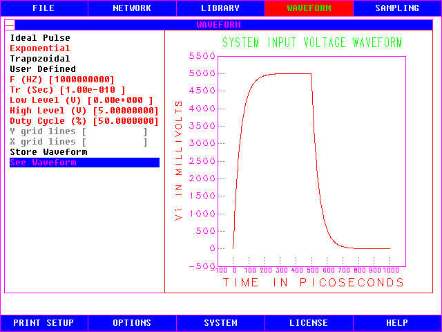
LINESCOPE virtually allows the use of any voltage
waveform of any shape or frequency (subject to the host
machine numerical limitations) as the clock source. This input
voltage signal can be defined by the user and applied at any
point on the network. Upon the completion of the analysis by
LINESCOPE, a user can observe Voltage, Current and Frequency
responses of the network at points of interest as well as line
impedance of each transmission line in the network as a
function of frequency. LINESCOPE
permits independent modification of the parameters of any
transmission line segment or other elements of the network.
LINESCOPE also allows inclusion of wave guides and Vias as
part of the network. There
is no limitation as to the geometrical dimensions of the lines
that are used in the networks simulated by LINESCOPE. This
feature makes LINESCOPE capable of simulating board level as
well as device level circuits.
Input
Parameters to LINESCOPE
The only input
parameters needed by linescope
are: transmission line geometry, line configuration,
interconnection pattern, physical
media parameters and input signal. There is no need for
the user to enter higher level parameters such as
line inductance, capacitance, impedance, time delays;
or perform field analysis of any kind.
LINESCOPE V.3.0
A
High Speed Simulator for High Frequency Applications
Other signal
integrity software perform a parasitic element computation or
use static finite element analysis to compute the static
transmission line parameters. These techniques do not compute
the actual distributed parameters as a function of frequency
which is nonlinear in nature.
LINESCOPE's
proprietary algorithm computes the distributed transmission
line parameters for every frequency content of the excitation
signal. As a result, LINESCOPE computes high frequency
phenomena such as inductive
and resistive skin effect with extreme accuracy, providing you
with the most accurate lossy line solution. This is a unique
and powerful feature of LINESCOPE which makes it ideal for
high frequency applications
even at extremely high frequencies (several Giga Hertz
and above).
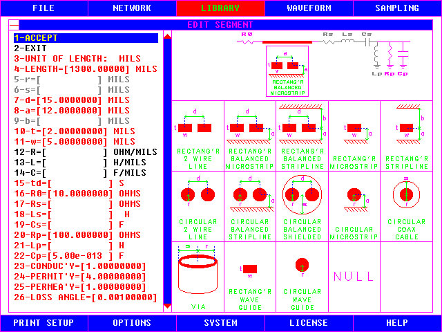
Lossy
Transmission Line Network Simulation
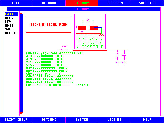
LINESCOPE provides the user with a library of the most widely used
transmission line configurations, such as: Balanced and
Unbalanced Microstrip or Stripline configurations with
circular or rectangular cross section, Coax cables, Vias, Wave
Guides, etc. You can create your own subset of these
libraries. Each library type can be conformed to your design
specification at the lowest level. User needs only to input
media and line parameters such as dielectric constant and line
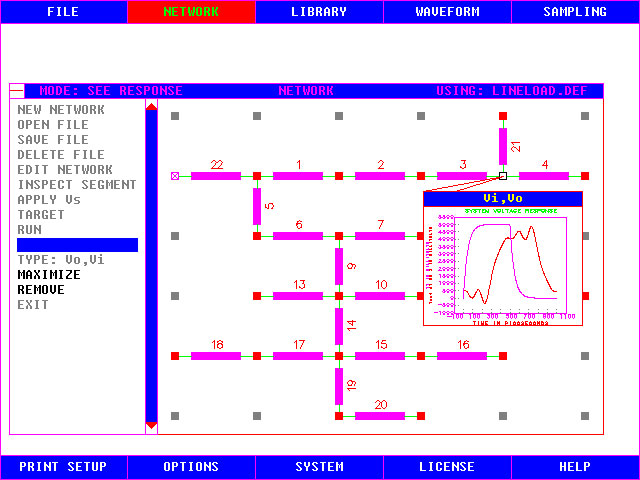
geometry dimensions. These transmission lines can be
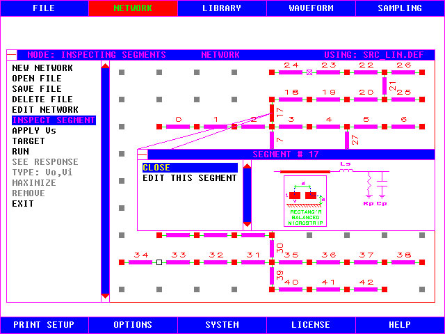
interconnected in any tree-like fashion to create the network
under test. Various types of lines can be interconnected
regardless of the configuration. User is able to change
any design parameter of any transmission line segment
independently and perform a new simulation until a perfect
design is obtained. All the transmission line segments in the
network are analyzed and solved as a lossy line taking into
account the high frequency phenomena such as skin effect,
group delays and dispersion, multiple reflections and
attenuation.
LINESCOPE's
Output Response Types
LINESCOPE provides the user with the following response types:
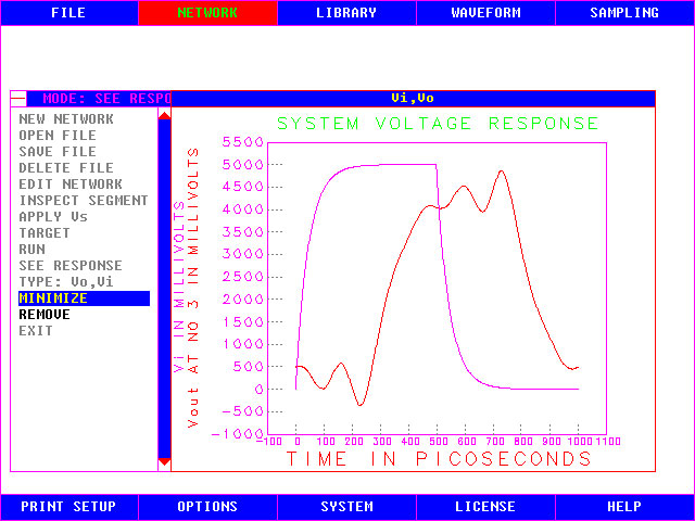
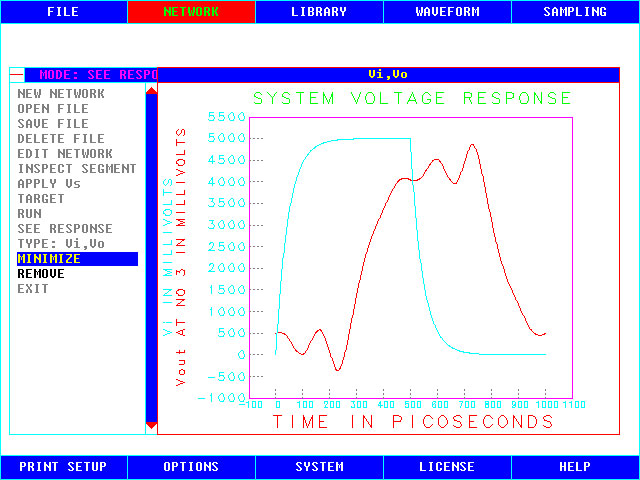
1.
Output
Voltage and Current Response waveforms at any node in the
network are displayed. You can observe any signal degradation
(Dispersion, Reflections, Attenuation, Delay, etc.) as you
would using an oscilloscope. However
LINESCOPE does not have the band width limitations of an
oscilloscope.
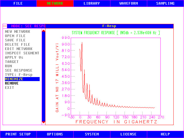
2.
Frequency
Response at any node in the network can be viewed graphically,
displaying the frequency response and band width of your
design at your node of interest.
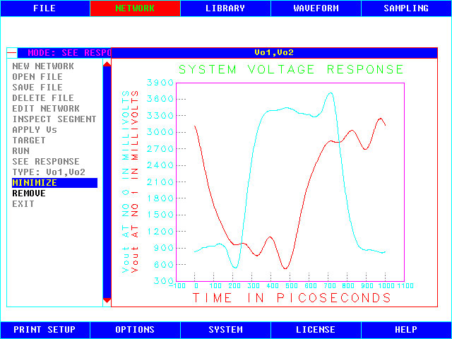
3.
Outputs
of various nodes can be displayed in one grid enabling you to
compare the signals and detect any
clock skews and time delays between various nodes of
interest quite easily.
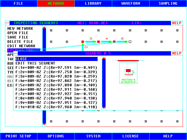
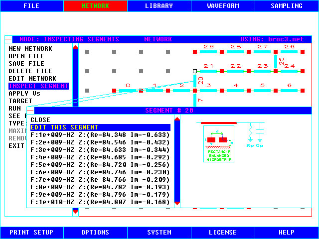
4.
Characteristic Impedance
values of any selected transmission line as a function of
frequency are provided. Both the real and imaginary components
of line impedance are provided for a range of frequencies.
5.
Frequency
spectrum of the input waveform is provided showing you the
bandwidth and the spectrum envelope of the periodic input
voltage waveform you are applying.
Accuracy
and Speed
LINESCOPE
uses a proprietary Lossy Transmission Line Network Simulation
method, creating an extremely fast and accurate solution to
even the most complex networks.
User does not have to perform any
electromagnetic field analysis or similar interim steps
when you use LINESCOPE. LINESCOPE performs a complete analysis
of the network and provides you with the crucial
time and
frequency domain responses of your network in one step in a
matter of seconds.
LINESCOPE is User Friendly
LINESCOPE is fully menu driven for ease of use. LINESCOPE user need not
learn any SPICE-like circuit description language to define
the network under test. LINESCOPE also has an extensive help
facility describing the various aspects of simulation with
LINESCOPE. User needs only to enter line geometry, select line
configuration, enter transmission line media parameters such
as dielectric constant and define an input waveform. LINESCOPE
provides a one step solution to all your signal integrity
problems. Any complex interconnection network can be
constructed usually in a matter of seconds just by a few
clicks of the
mouse. LINESCOPE's advanced graphical user interface makes it extremely simple to use.
LINESCOPE's
Graphical User Interface
LINESCOPE is equipped with a powerful graphical user interface.
Various aspects of LINESCOPE such as Menus, Networks,
Transmission lines and Waveforms are all shown in full VGA
color for ease of use. LINESCOPE can also print various items
of interest directly from the screen into the supported Color
and Black & White printers, thereby allowing the user to
obtain a hard copy of various items of interest such as
network configuration screens and output response waveforms at
various points of the network.
Expert
Technical Personnel
LINESCOPE is supported by expert technical staff at Advanced Scientific
Applications specialized in the field of High Speed
Signal Integrity and Electrical Performance Simulation.
LINESCOPE's
Platform Requirements
Operating
system:
Windows:95+/98/2000/NT/XP+/MS-DOS Version 3.0 or higher
Hardware:
IBM PC or compatibles, 386+ (386, 486, etc.), MS-Mouse or
compatible, VGA Monitor and Video card
Memory
Requirements:
256Megabytes of RAM or MORE
Disk
Space Requirements: 35 Megabytes (Minimum)

Key
benefits

 |
Significantly shorter time to create designs |
|
Real-Life scenarios and instant what-if simulations |
|
Reduced development cycle costs |
|
Exact Responses, No Approximations |
|
User Friendly GUI reduces training time and costs |
|
Full Support for Team Design allows multiple designers and layout engineers to work in parallel
|
|
Ideally suited for highly-constrained designs with critical paths in, FPGAs, backplanes, packages, PWB, PCB, Silicon, IC's, Cabling, VIAs, etc.
|
|