Advanced Unified Modeling Language Tutorial
Since the turn of the millennium, I have been experimenting with the Unified Modeling Language to see how effective it really is in documenting software architecture and design. With the release of UML 2.0 in 2007 (and as a results of all the practice that I have had over the past seven years), I am fully convinced about the expressive power of UML. It is now eminently possible to capture the ideas and essence of software architecture in crisp and clear UML diagrams.
Of course, this requires significant maturity in the art of “modeling” (i.e. the art of taking real world concepts and representing them in the object-oriented computer world) and to a lesser extant requires mastery over the capabilities of UML 2.0.
Every software professional has, at some time of other, tried his / her hand at class diagrams and sequence diagrams, but the real power of UML lies in diagrams other than these. Some of the lesser known (and more powerful) UML diagrams are – package diagrams, component diagrams, deployment diagrams, and composite structure diagrams. Even the sequence diagram has been upgraded with some elegant new constructs that raise its expressive power a couple of notches.
If the average software professional learns to use these diagrams effectively, it will go a long way in halting the commoditization of the software profession.
Having said that, I need to reiterate the point that maturity in the art of modeling is essential for effectiveness and that comes only with time and practice.
“Practice makes perfect, gonna get it right,
gonna get it right,
One night at a time”– George Strait
Over the next few days I will post some examples of the power of these diagrams (see Pages on the right). Most of my examples will come from the Insurance (P&C and Health) space, but since this space is relevant to all and is intuitive, I hope my readers will not have much trouble understanding them.
Public Health System in India
The public health system in India has a well defined structure. While the quality of implementation of this system may be questionable, the structure is extremely well defined as can be seen by the models I present here.
There are three levels of healthcare provided to rural populations: Sub Centers and Primary Health Centers provide primary care and Community Health Centers provide basic secondary care. The following model depicts the population guidelines that govern the formation of these rural health care centers. We have also included some statistical information in the model in the form of some Notes and the Village class.

Rural Healthcare System in India
A Sub Center is the most peripheral and first point of contact for the rural population with the public health system. The following models the staffing of a Sub Center:

Sub Center Staffing Model
A Primary Health Center provides an integrated curative and preventive healthcare to the rural population. The following models the staffing of a Primary Health Center:

Primary Health Center Staffing Model
A Community Health Center provides basic secondary care to the rural population including surgical intervention. The following models the staffing of a Community Health Center:
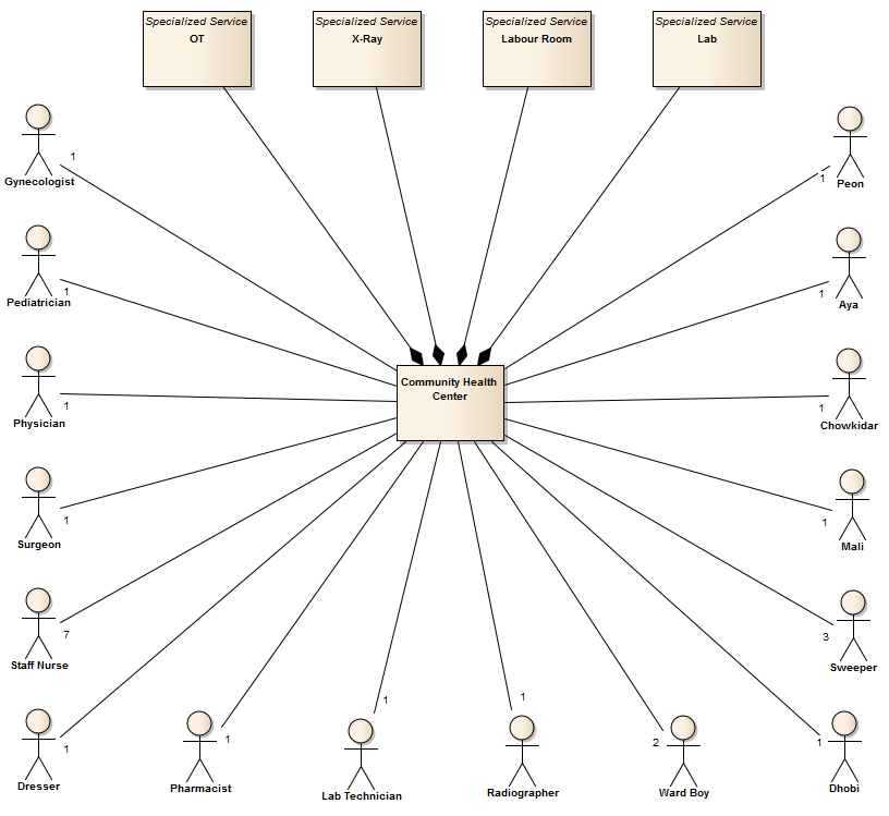
Community Health Center Staffing Model
As always, a picture is worth a thousand words!
Indian Army
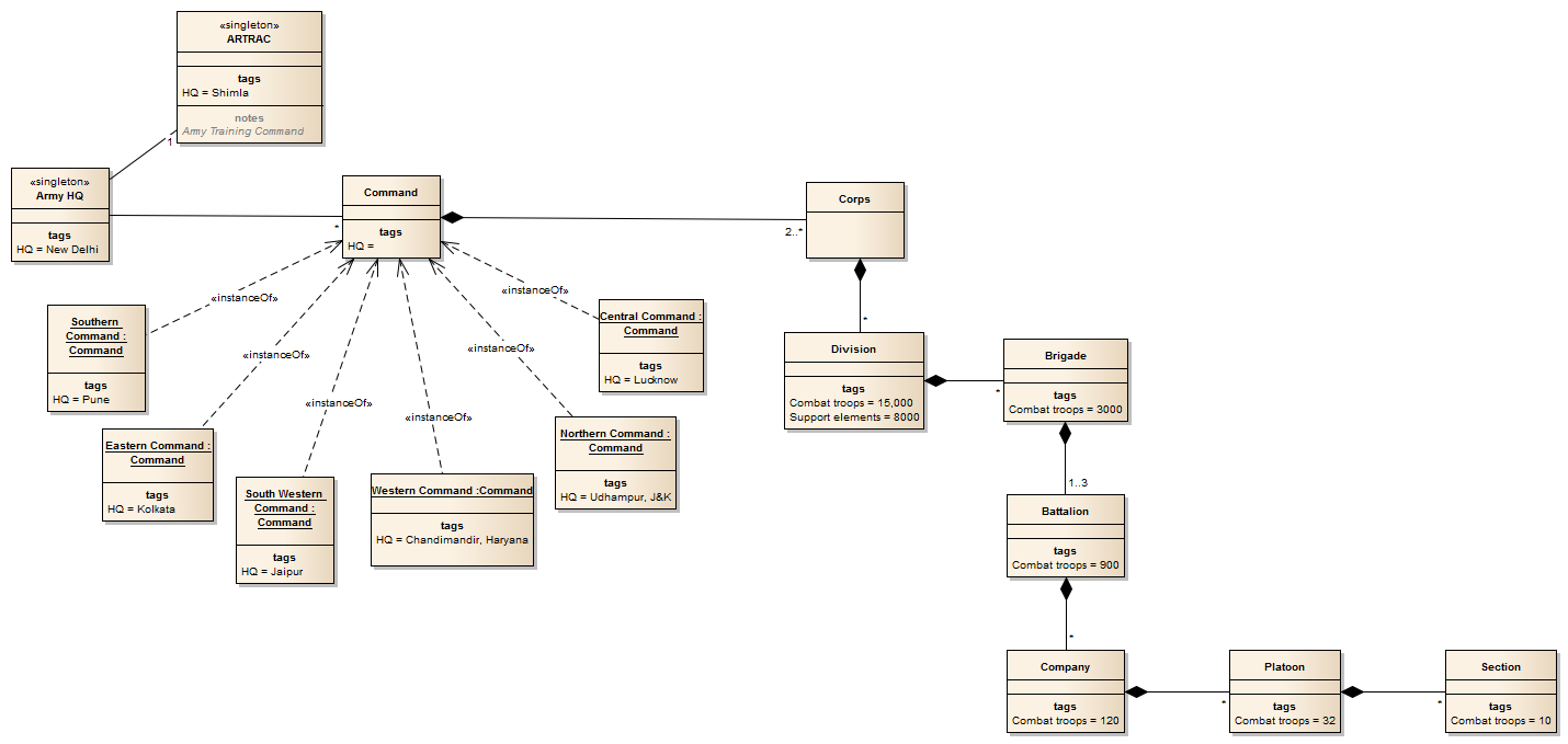
Researching the 1962 Sino-Indian war, I realized that understanding the events leading up to that war necessitate an understanding of the organization structure of the Indian Army. And the structure of the Indian Army is best represented using various UML diagrams!
First, the class model of the various field formations of the Indian Army:
Next a use case diagram (containing only actors) showing the various designations:

Finally, a structure diagram which emphasizes the hierarchical nature of the field formations and the reporting:

An entire ERP system in a single diagram
I found a lovely structural breakdown of ERP on the Technology Evaluation Centers web site. Their motivation in breaking down ERP is to compare multiple ERP products in a meaningful fashion.
While the TEC web site uses a tree control to allow users to navigate through the capabilities of ERP software, my interest is in creating a UML representation of the same. Here is what I came up with:

I do not have the patience to create the 3000+ use cases that reside in these many packages, but if someone is looking for what is broadly in the scope of the term “enterprise resource planning”, this diagram is very illuminating.
Thank You, All My Readers!
After a short five months, thanks to all you readers, this blog has crossed 10,000 hits today!

My sincere thanks to all of you!
Deployment Diagrams – Communication Paths
I have found the concept of communication paths in UML deployment diagrams to be quite frustrating for the simple reason that a communication path connects two deployment targets and no more than two. In other words, communication paths do not support the familiar concept of a “bus” / LAN / “high-speed backbone” to which multiple devices are connected.
As a result, while deployment diagrams are very expressive when it comes to portraying devices and nested execution environment and deployed artifacts, when it comes to showing connectivity between devices, they fall short.
After living with this problem for a long time (I pretty much stopped illustrating connectivity between devices), I hit upon the simple idea of modeling a “bus” / LAN / “high-speed backbone” as a node (not a device). This way, I am now able to connect multiple devices to this “bus” / LAN / “high-speed backbone”!
Structure of Deployment Models
Deployment models, while being very expressive, are not easy to organize and manage. Any non-trivial deployment model would require a multitude of devices, execution environments and artifacts (and multiple instances of these) which typically makes the organization of a deployment model somewhat hard.
The following package diagram represents a typical model organization that I have found useful in the J2EE space:
Read more…
Architecture Drivers and Decisions
As a solution architect, I always like to base key architectural decisions on specific architecture drivers. For example, a decision to use an AJAX-based UI would depend on the need to support low-bandwidth connections (that’s right, being a business application developer, I am less interested in the richness of AJAX and more in the fact that only data moves on the wire). And I like to convey these decisions via UML diagrams.
But this post is not about UML diagrams.
 This connection between drivers and decisions is not unique to software development. Here is an interesting example from the the British Everest expedition of 1953 that put Edmund Hillary and Tenzing Norgay on top of Mount Everest:
Class Model in a Corporate Annual Report
I was leafing through the Annual Report of DLF – a leading real estate company in India – and saw the following diagram in it:

DLF Business Units
If you are proficient with modeling, you will immediately see this a nothing but a class model!
I continued reading through that report and finally derived the following model of their business:

DLF Business Units - Class Model
Quite a large business and I am not sure I got it entirely right. Further, each individual hotel / home / office construction is constituted as a separate company (DLF has 243 subsidiary companies)! I have not even attempted to model that – I have stopped with business units and joint ventures.
Why attempt such a model at all? You should ask that question to the guys from Ramco whose Ramco ERP is the ERP platform for DLF!
Granularity of Use Cases
I have seen many newbies struggle with a basic question of how granular use cases should be. I will try to address that question in this post.
Conventional wisdom as articulated in various books [Use Cases: Patterns and Blueprints] and articles [Use and Abuse Cases] argues that functional decomposition of use cases to derive smaller, more fine grained use cases is bad, if taken too far. Most literature is concerned with preventing the “explosion” of use cases.
How far is too far? What is “explosion”? The answers to these questions are tied to another question – “what do you intend to do with your use cases?”
What a Month in the Financial Sector!
In my Advanced UML Tutorial so far, I have not shown any examples of object diagrams (except for composite structure diagrams, which are a special case of object diagrams).
To make us for that lacuna, I model a current hot topic using UML object diagrams.
This month has been one of tremendous flux and turbulence in the global financial sector. Lehman Brothers has gone under and been subsequently dismembered and sold to Barclays and Nomura Holdings. Merrill Lynch was snapped up by Bank of America. In Europe, a series of consolidations have happened without much fanfare.
Is it possible to depict who-acquired-who using UML?
About Me

Hit Counter

