Final Project: Therapeutic Glove/(Torture Glove)

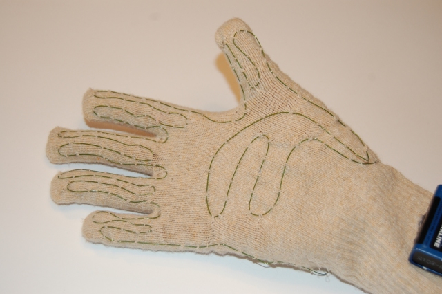
For our final project, Julia, John, Dan and I wanted to expand upon Julia’s fantasy device from earlier in this semester and create a glove that could alleviate hand pain and tremors for people suffering from arthritis and Parkinson’s disease. The three things we wanted to make happen were to: have a heating element, use a vibrating motor to massage the top of the hand, and create compression around the hand to flatting and stabilize the fingers.

We initially started working with a Lilypad Arduino, with the hopes of making the whole unit as compact and portable as possible, but after frying the Lilypad we learned an important lesson about prototyping: things will break, wires can be the broken component in a circuit, and the first incarnations will be bigger/more cumbersome than we would like.

The basic components of our glove are:

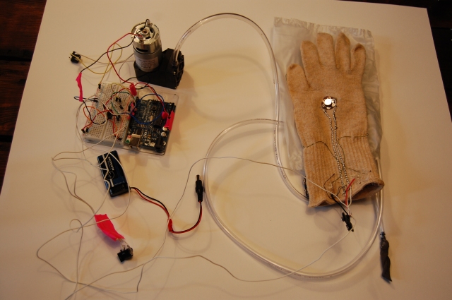
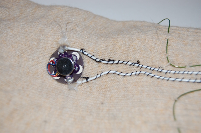
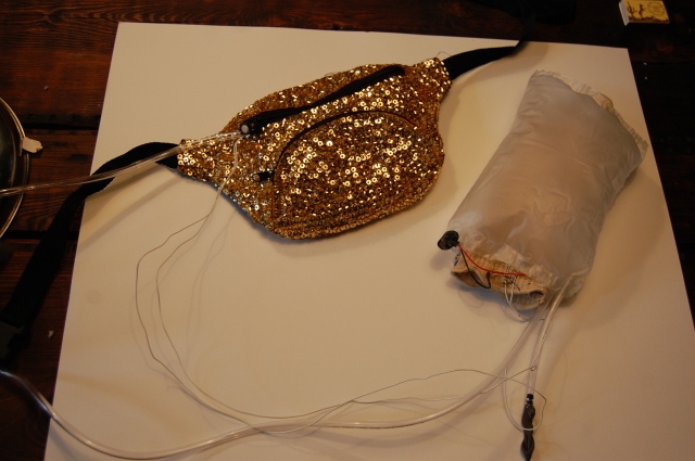
compression glove, Arduino Duemilanove, teflon wire, Lilypad vibration motor, compact air pump, vinyl air bladder, and aquarium tubing.

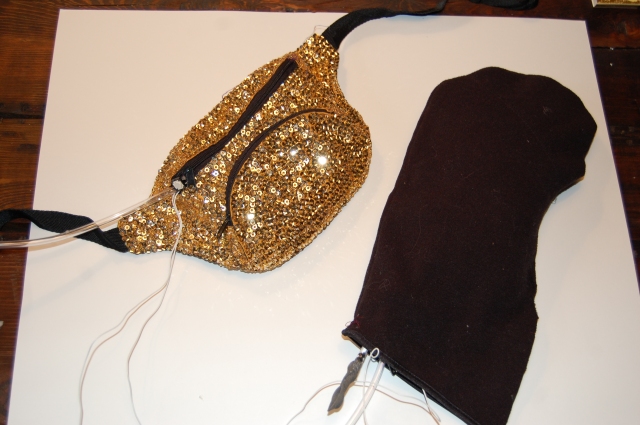
The whole thing was powered by two 9v batteries and one 12v wall AC adapter. We also made a black fleece cover for the hand part and stored the power sources and microcontroller in a fashionably sequined fanny pack.

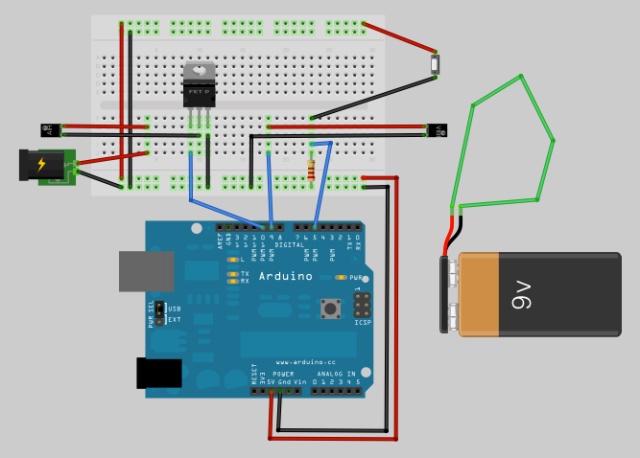
Here is a diagram of our wiring:

In this diagram, the two small components are the air pump and vibrating motor. The green wire connected to the 9v battery represents the teflon wire.

Here is our group diligently working:

And here are photos of our final project:

Posted in Assignments | Leave a comment

Lab: Multiple Serial Output

I used an accelerometer and a push button as my two sensors.

When the line of code read Serial.println(analogValue, DEC); the number that read on the serial monitor was 489 when my breadboard was not moving, and ranged from 300-700 when i shook it around.

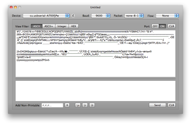
With the line of code as Serial.println(analogValue, BYTE); the serial monitor was going all over the place with all kinds of characters when I was moving the breadboard around, and at rest it seemed to like this character best:

Î

So I just noticed, the given code in step #3 is incorrect, in the line that reads analogValue=analogRead(analogPin); under the void loop() should have the “/4” before the “;”. That is why my readings were not between 0 and 255 like they were supposed to be. When I added the “/4” to the code, the DEC I got numbers within the expected range and with BYTE I got characters that were much less obscure than the first go around.

With step #4, sending the data in many formats, my serial read turned out like this:

success!

Next I tried the Punctuation method and read it through Cornflake Serial monitor and then through the given Processing sketch. Also success.

Now I tried the Handshake method

Posted in Labs | Leave a comment

Lab: Serial Output

Here is my serial garbage in Cornflake:

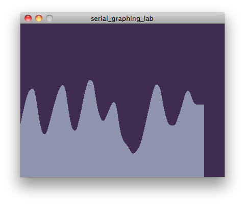
I imported the processing serial library and followed the example code and here is the lovely example of my graphed serial data:

Woo I’m reading serial input!

Posted in Labs | Leave a comment

Media Controller

Arduino Code:

void setup() {
Serial.begin( 9600 );
pinMode( 2, INPUT );
}
void loop() {
int accelX = analogRead( 0 );
int accelY = analogRead( 1 );
int switchState = digitalRead( 2 );
Serial.print(accelX, DEC);
Serial.print(“,”);
Serial.print(accelY, DEC);
Serial.print(“,”);
Serial.println(switchState, DEC);
}

Processing Code:

import processing.serial.*;Serial myPort;
int state = 0;float xpos, ypos;
void setup() { size(1200, 700); background(1); println(Serial.list()); myPort = new Serial(this, Serial.list()[0], 9600); myPort.bufferUntil(‘\n’);}
void draw() {
fill( 0, 100, 150 ); stroke( 255, 255, 0 ); if(state == 1) {   ellipse(xpos, ypos, 10, 10); }}
void serialEvent (Serial myPort) { String myString = myPort.readStringUntil(‘\n’);
if(myString != null) {   myString = trim(myString);   int sensors[] = int(split(myString, ‘,’));
for(int sensorNum = 0; sensorNum < sensors.length; sensorNum++)   {     print(“Sensor ” + sensorNum + “: ” + sensors[sensorNum] + “\t”);   }
println();
if(sensors.length > 1)   {     //print(“hello”);     xpos = map(sensors[0], 250, 375, 0, width);     ypos = map(sensors[1], 370, 250, 0, height);     state = sensors[2];   } }

}

Posted in Uncategorized | Leave a comment

Stupid Pet Trick: Kelis makes you a milkshake

Digging through my desk drawer, I found this freebie Kelis cd I got in a gift bag from fall fashion week. Not really being a Kelis fan, I was going to throw it away but decided to open it up at the last minute. I am so glad I did, to find this gem:

Kelis is best known for her 2003 euphemistic hit “Milkshake”

So what I wanted to do was have sphinx-kelis make me a milkshake:

Posted in Assignments | Leave a comment

Lab: Tone Output

Like the servo labs, this was pretty straight forward but fun. Here is the video:

Posted in Labs | Leave a comment

Lab: Servo/Analog Out

This was fun. I hooked the servo up first with a potentiometer and then the pressure sensor. The pressure sensor was more fun to play with, since the potentiometer was limited in speed by how fast I could turn the dial. It is significantly faster to change pressure in between two fingers than it is to turn a dial. Here are 2 videos of each sensor:

(I added post-it flags to the servo for dramatic effect)

potentiometer

pressure sensor

Posted in Labs | Leave a comment

Lab: Electronics

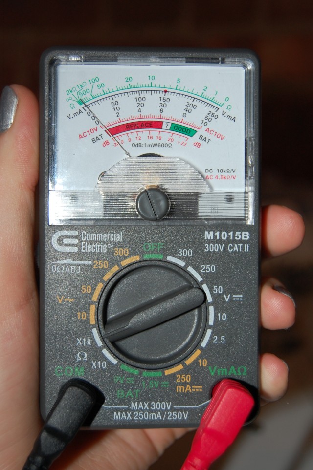
Analog Multimeter

Measuring Continuity

I used an analog multimeter for this lab, so I needed to figure out how to test for continuity since it is different from the digital example. For testing continuity on this multimeter, there is no separate test setting, so I just turned the dial to the “ohms” section, on either “X1k” or “X10” and if there was continuity, the needle jumped to the opposite side of the scale, at zero ohms.

When I touch the leads to a single piece of wire, there is continuity, but with the switch there is none until the button has been pressed. This makes sense since the switch would only complete a circuit if engaged. When I put two wires in the breadboard at random, the needle moves slightly, but of course when the wires are in the same row the needle does a full jump. I did not expect to see any reading from the two wires at random, but I am not sure why that would happen. (edit: I tried this again without having any part of my hands touching the leads or wires, and then there was no effect. This now makes sense because when I tested for continuity across my hand, the needle would move slightly too).

Resistance of a Component

Set the dial to X10 ohms, and got a reading of 220 for the resistor we use for LEDs. correct!

Measuring Voltage

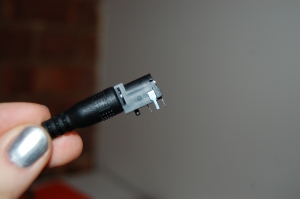
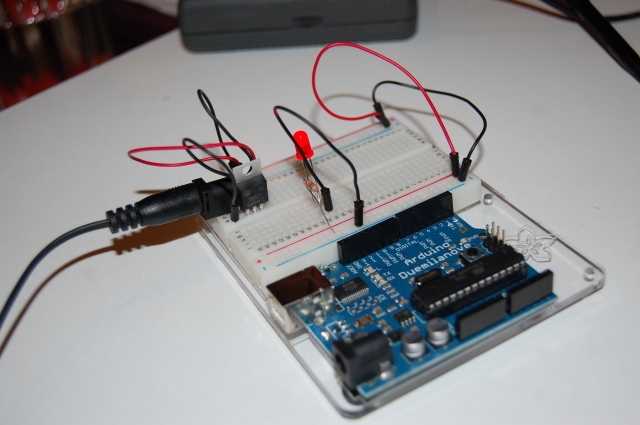
I had some difficulty figuring out exactly how to set up the breadboard with the nifty doesn’t-necessarily-need-wiring DC jack, but I used the multimeter to figure out which of the 3 pins on the jack were positive and negative. (note: pin on the back of the barrel=hook up to pos and pin in the middle of the barrel=hook up to neg). After getting the circuit set up, I tested for voltage and got a reading of 2 volts across the LED. So I guess the resistor is eating up 3 volts of the 5v in the circuit.
A Basic LED Circuit

Voltage across the switch (not pressed): made the LED light up dimly and got a reading of 3. Voltage across the switch (pressed): LED lit up fully and reading of 0. Voltage across resistor (switch pressed): 2. Voltage across LED (switch pressed): 2.  Adding up the totals of the engaged switch, resistor, and LED, I get 4 volts. So 1 volt is lost as light from the LED.

Components in a Series

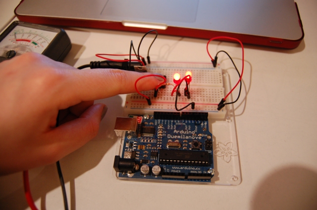
Wiring up 2 LEDs with a switch in a series configuration resulted in the following voltage measurements (and two dimmed LEDs). Voltage across resistor: 1. Voltage across first LED: 2. Voltage across second LED: 2. Voltage across power and ground (switch open): 5 and (switch engaged): very slightly less than 5. This last piece of data makes me question my addition in the basic LED circuit measurements, since I think this indicates that significantly less than a full voltage is lost in lighting up the LEDs.

When I added a third LED, to my surprise it did light up. I did not expect this to happen and when I measured for voltage across each LED, I came up with slightly less than 2 volts each. This makes just about 6 volts between them, but measuring over power and ground I still have 5 volts. Adding a fourth LED resulted in none of them lighting up, which makes sense because the voltage drop is too great across 4 LEDs for 5 volts.
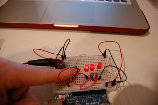
Components in Parallel; Measuring Amperage

The voltage across each LED in parallel were all just a little less than 2. As for measuring amperage, I am still having difficulty figuring out exactly how to do that within the circuit. I’ll try again later.
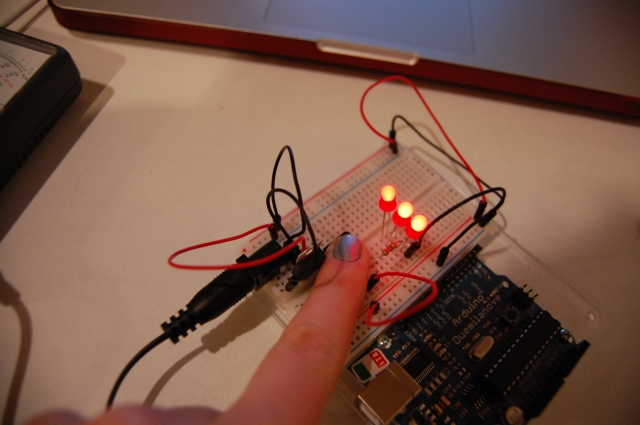
Variable Voltage with a Potentiometer

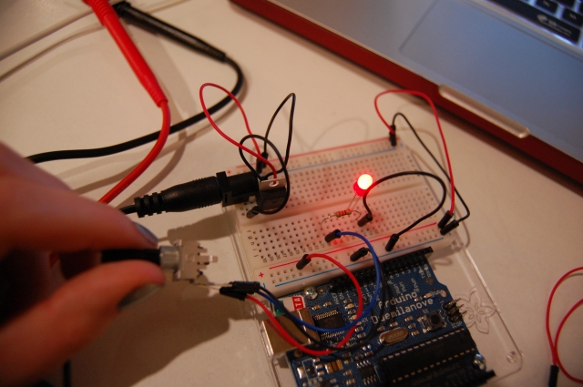
One thing I noticed with measuring the voltage in the LED as I turned the potentiometer is that there was only a very small drop in voltage from the full brightness and halfway turned potentiometer. However, when I measured the voltage across the power and ground leads on the potentiometer, there was a steady drop in voltage from 5v when the LED was completely off to 4v when the LED was at full brightness.
Posted in Labs | Leave a comment

Fantasy Device: Scent Capture/Printer

Smells are strongly tied to memories, but they tend to be fleeting (at least the good smells) and difficult to replicate without the item from which it emanates. What I would like to have is a handheld device with a receptor that captures a scent, but also has the ability to “print” the scent onto a strip of paper.

When I think about the receptor that would best capture scent, I think of hair. Anyone with long enough hair knows its proclivity to retain smells. So a tassel-like receptor made up of very fine strands of sensors with the ability to recognize and capture the molecules that make up a particular smell. This analog information collected could be turned into data that can be stored by a computer through interpreting the molecular conglomeration and recording the pattern. Once captured, the scent can be named and then printed onto a strip of paper, using the stored molecular pattern as a guide for a reserve of raw materials contained in the device.

The physical interface of the device would include a large screen with an onscreen keyboard that appears for naming and searching the reserve of your scent library. Aside from an On/Off button, other functions (“collect scent” and “print scent”) would be controlled through the prompts on the screen. Inside of the unit there is a space for a small cassette of rolled paper, vials of the molecular substrates used to create the scents and mechanics of the printing system, which I imagine to be like an inkjet printer.

Posted in Assignments | Tagged | Leave a comment

Getting Creative! [Analog In Lab]

Posted in Uncategorized | Tagged | Leave a comment